
Green hydrogen is an effective way of storing renewable energy, paving the way toward a more sustainable future. Among the three main electrolysis technologies used for hydrogen production, solid oxide cells (SOCs) are the most efficient, yet also the least mature. Bringing such emerging technologies closer to market is a key goal of the H2SHIFT project.
H2SHIFT (Horizon Europe project, ID 101137953) aims at establishing the first open innovation test bed for innovative hydrogen production technologies, catering to startups and SMEs. The analysis presented here is part of a project showcase, “Ultra-compact 3D printed SOEC stack”, developed jointly by the project partners. The 3D-printed cells were co-developed by H2B2 Electrolysis Technologies, the industrial partner behind this configuration, and IREC (Catalonia Institute for Energy Research). The stacks were then printed and tested at IREC, leader of Test Line 1 (TL1). The structural analysis was performed by Resolvent, leader of Test Line 8 (TL8), in collaboration with IREC.
This 3D-printed configuration, which leverages corrugated electrolyte surfaces, has been shown not only to reduce the size of cell stacks, but also to improve their efficiency [1]. However, the full stack assembly of the new SOC configurations has not yet been analyzed from a mechanical perspective, and it is not known how well this configuration can withstand the mechanical loads. Accordingly, this blog post is dedicated to presenting the methodology and the results of a mechanical analysis of these 3D-printed SOCs. The study explores two configurations: (1) during assembly and (2) during operation.
One configuration for stack assembly is depicted in Figure 1, wherein the assembly consists of 18 single repeating units (SRUs). To ensure the correct working conditions of the system and the proper sealing, two compression plates sit at the top and bottom of the stack which are compressed by the surrounding structure and the connecting tie-rods.
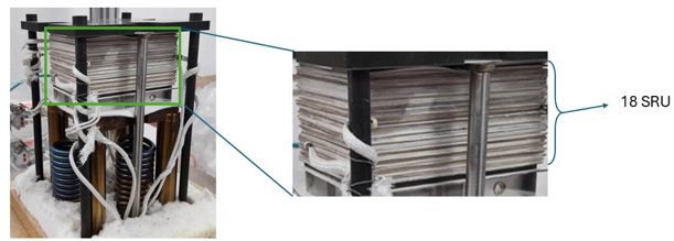
Figure 1: Stack assembly and the supporting structure taken from [1]
Each SRU consists of a corrugated electrolyte coated with thin fuel and oxygen electrodes, two meshes, two seals, and an interconnect, the last of which provides electrical connection between the cells. The half-exploded view of the SRU is shown in Figure 2. In comparison with the straight electrolytes in the conventional SOCs, the corrugated ones provide higher surface area within a specific space, thereby increasing the throughput. The SRUs are stacked on top of each other, with flat interconnect plates in between. One of the benefits of the corrugated electrolyte configuration is the possibility of using a relatively thin interconnect layer, which can considerably reduce the mass and cost of the stack assembly.
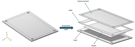
Figure 2: SRU 3D model consisting of corrugated electroyte and the layers on top of it. The explosion view only shows the components on the top of an SRU. A similar pattern of plates exists at the bottom
The computational domain for a single SRU, as well as the compression plates from the supporting structure, are shown in Figure 3a. All the SRUs are stacked on top of each other and the applied load aligns with the stack axis (z-direction in Figure 3b). As a result, all SRUs are subjected to the same load and only a single SRU is considered in this computational study. Additionally, since a single SRU is close to being symmetrical in different directions, only one-quarter of a single SRU is modelled. However, the small asymmetry in the x-y plane (refer to Figure 2) is taken care of by simulating both halves and then considering the case with higher stresses.
Figure 3b shows the applied boundary conditions. The load is applied as a prescribed displacement boundary condition. This is due to the highly non-linear contact problem, in which the prescribed displacement is more stable than the applied-force problem. Additionally, in order to improve the problem stability and convergence, the displacement is ramped linearly from zero until the computed load equals the applied physical load.
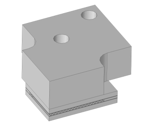
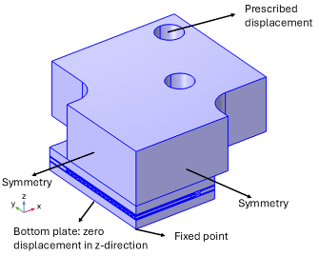
Figure 3: a- Computational domain, and b- Boundary conditions
All the other external boundaries that are not mentioned in Figure 3b are free boundaries. The internal boundaries, which are the boundaries between the components, are set to contact boundaries, some of which are also exposed to friction conditions to avoid non-physical sliding.
Results
The results are provided and discussed for two scenarios. The first is the assembly scenario, for which the mechanical state after applying the compressive load is studied. This state does not account for the working conditions, meaning that no thermal load is applied on the system. The second scenario investigates the operational condition, which also takes into account the thermal load resulting from the hot fluids flowing through the system, causing thermal expansion of the components.
Scenario 1: Assembly state
Figure 4 shows the displacement field in response to 3 loading conditions of 2.5  , 3.5 , and 5.5 for the prescribed displacement. The resulting force from the prescribed displacement of 3.5 is approximately equal to the realistic force that is applied on the system. The other two loading conditions represent cases when the applied load is increased or decreased relative to the realistic load. In Figure 4, the maximum absolute displacement takes place in the free-hanging region of the compression plate, and the minimum displacement, as expected, takes place close to symmetry planes.
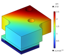
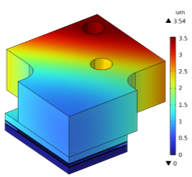
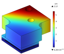
Figure 4: Absolute displacement field for three loading scenarios of a- applied displacement of 2.5 μm , b- applied displacement of 3.5 μm, and c- applied displacement of 5.5 μm
Figure 5 illustrates the first principal tensile stress on the corrugated surfaces for the same 3 loading conditions described above. Since the electrolyte is made of ceramic, for which the compressive strength is much larger than the tensile strength, and it is not expected to fail under the compressive load, the color scale is truncated to only depict the tensile stresses. It can be seen that the maximum value for the first principal stress is taking place on the corrugated surfaces close to the external edges.
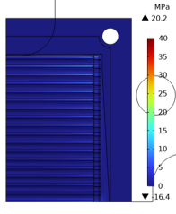
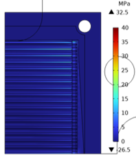
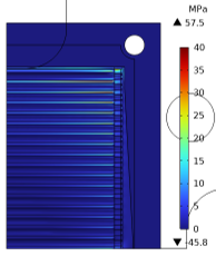
Figure 5: First principal tensile stress on the corrugated electrolyte and its surrounding plate for a- applied displacement of 2.5 , b- applied displacement of 3.5
, and c- applied displacement of 5.5
In order to assess the failure of the components, the Weibull failure probability is used which reports the reliability of the parts and the probability of the failure. The Weibull parameters of the electrolyte ceramic are found from the literature [2]. Table 1 reports several output values for the different loading conditions and the possibility of failure for each case. As the developed stresses are quite low relative to the strength of the material, the failure probability is almost zero for all the 3 cases under the assembly-state conditions, showing the stack is quite reliable under these conditions.
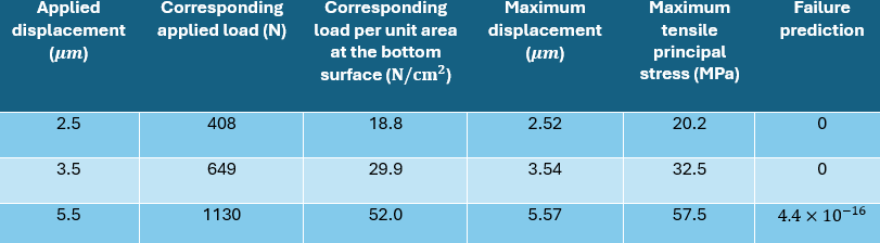
Table 1: Comparing force, stress, and failure output variables for the 3 loading conditions of 2.5, 3.5, and 5.5 prescribed displacements for the assembly-state conditions
Scenario 2: Operational conditions
Operational conditions refer to the state of the device while it is working and the hot fluid flows through the cells. Depending on the placement of the insulation materials, the temperature field can develop differently within the different components. Additionally, the stack consists of different materials with different thermal expansion coefficients, which contribute to the different thermal expansion within the different components. Depending on how the components are attached together, the difference in thermal expansion through the components can lead to either risk of leakage of the fluids within the system or high stresses in the components.
To tackle this challenge, a spring is considered between the bottom of the lower compression plate and the end of the tie rods, as depicted in Figure 6. Depending on the temperature within the components and their thermal expansion, either the stack or the tie-rod can expand more than the other. Considering also the stiffness of the spring, the four scenarios that can happen are summarized in Table 2. When the thermal expansion in the tie-rods is more than the stack, as depicted in Figure 6a, there is a risk of fluid leakage as the compression load becomes smaller. In such a situation, a high-stiffness spring will keep the compression load on the stack.
On the other hand, if the thermal expansion is larger in the stack, depicted in Figure 6b, the compression load would increase between the compression plates and the tie-rod, potentially leading to failure of some of the components. A spring with lower stiffness can allow some relative motion between the tie-rods and the stack, mitigating the effects of very high stresses. Conversely, a spring with high stiffness can lead to high stresses with potential damage to the components.
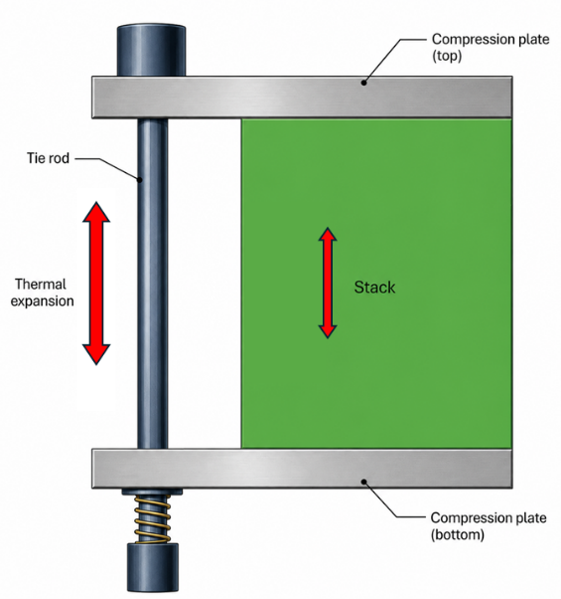
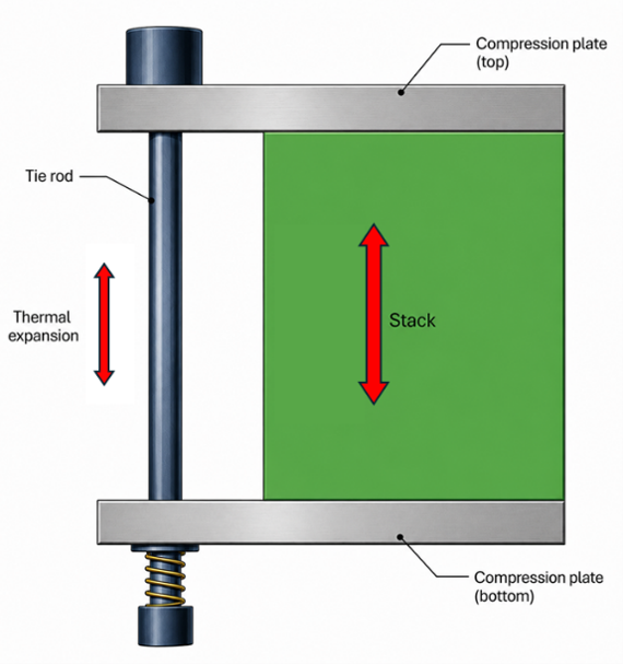
Figure 6: Schematic of the stack and tie-rod assembly (a) when thermal expansion is higher in the tie-rod, and (b) when thermal expansion is higher in the stack

Table 2: Different scenarios for the relative expansion between the tie-rods and the stack with different spring stiffness
Since the hot fluid goes through the stack, the possibility of higher temperature within the stack and the occurrence of situation (b) in Figure 6 is higher. For such a situation, a careful adjustment of the spring stiffness is necessary for the desired function of the system. In this blog post, the worst-case scenario in which the spring stiffness is equal to the tie-rod stiffness is investigated. For such a scenario, it can be assumed that the bottom end of the tie-rod is directly attached to the bottom compression plate, as depicted in Figure 7.
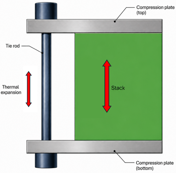
Figure 7: Schematic of the worst-case scenario where thermal expansion in the stack is higher than in the tie-rod and the spring is very stiff. In this extreme case, it is assumed that the spring stiffness is as high as the tie-rod itself, so the spring is removed.
Similarly, different thermal boundary conditions can be assumed for the system. For the sake of conciseness, it is assumed that all the components of Figure 7 are included within the same chamber which is insulated from the environment. This will lead to quite a uniform temperature within the assembly, but still there is a temperature difference between the tie-rods and the stacks. Based on a preliminary thermal analysis with these assumptions and taking into account the thermal expansions of different components, an overall temperature difference of 25  between the tie-rods and the stacks is considered. This would lead to a 38.8- difference in the vertical thermal expansion between the tie-rods and the stack assembly, if they were free to move. However, since they are constrained, the difference in the expansion between the tie-rods and the stack assembly emerges as extra load on both the tie-rods and the stacks, emerging as traction in the former and compression in the latter. The resulting first principal stresses on the corrugated plane (only tensile) is depicted in Figure 8, where it can be seen that the thermal load causes a stress development of more than one order of magnitude higher than the case without the thermal loads.
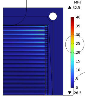
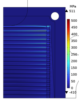
Figure 8: Comparison of the first principal stress for (a) the assembly-state scenario without the thermal loads, and (b) the working conditions with the thermal loads.
The resulting forces, stresses, and the possibility of failure for both cases of with and without the thermal loading for a boundary displacement load of 3.5 are depicted in Table 2. It is interesting to note that, while the possibility of failure is almost zero for the case without thermal loading, it increases to 4.1 % when it operates under the working conditions, with the assumption that the tie-rods and the compression plates have a fixed contact.
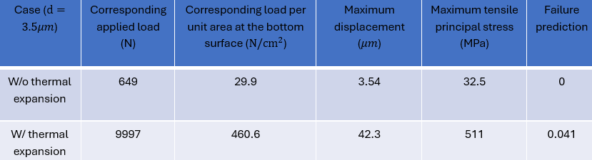
Table 3: Comparing force, stress, and failure output variables for two scenarios of assembly-state (W/o thermal expansion) and working conditions (W/ thermal expansion)
While there are other scenarios that can be applied to mitigate the failure possibilities under operational conditions, the current study underlines the importance of the thermal gradients and temperature differences between the different components in predicting the reliability of the device. Choosing a spring with computed stiffness can reduce the stress level within the system and reduce the possibility of failure.
Conclusion, learnings, and possible developments
In this study, the mechanical behavior of a stack of SOCs with a new design, consisting of 3D-printed corrugated electrolyte has been investigated. The numerical analysis was conducted for two scenarios of assembly-state and operating conditions. The results showed that the stresses are much smaller than the strength for the assembly-state conditions, suggesting that the possibility of failure under this condition is low. On the other hand, stress is more than one order of magnitude higher for the operating conditions under certain assumptions, due to the thermal expansion, showing a 4.1% possibility for failure. It is, however, possible to reduce the stress related to the operating conditions by accommodating the effects of thermal expansion in the assembly.
References
[1] S. M. R. P. W. Z. S. A. M. N. L. B. J. B. M. T. A. T. A.M. Martos, “3D printing of reversible solid oxide cell stacks for efficient hydrogen production and power generation,” Journal of Power Sources, p. 234704, 2024.
[2] F. W. N. L. C. S. S. S. Ilaria Bombarda, “High temperature tensile strength of ultrathin 3YSZ tapes: An experimental study combining Weibull theory and fracture mechanics,” International Journal of Hydrogen Energy, vol. 164, p. 150764, 2025.