Alkaline water electrolysis is a well-established and cost-effective technology for producing green hydrogen. However, challenges such as flow maldistribution, gas accumulation, and uneven electrochemical performance across the stack still limit its scalability. To address these issues, a multiscale and multiphysics simulation framework has been developed using COMSOL Multiphysics®. The framework integrates high-fidelity computational fluid dynamics (CFD) with reduced-order models (ROMs), enabling efficient and accurate simulations at both the cell and stack level.
The goal is to support performance optimization, reduce computational time, and pave the way for iterative design and real-time diagnostics. The framework is demonstrated on a 7-cell commercial-scale electrolyzer stack, each with a diameter of 0.35 meters. This approach facilitates rapid evaluation of design variations while preserving the essential physical behavior required for accurate system-level analysis.
Methodology
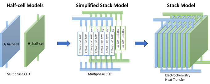
The simulation framework is modular and hierarchical, composed of three tightly coupled layers. Each layer reflects a different physical scale, yet all are integrated to ensure seamless propagation of relevant parameters from local to global scales.
1. Half Cell CFD Models
The simulation framework begins with detailed CFD models for both the hydrogen and oxygen half-cells. These models incorporate two-phase flow, using the standard k-ε turbulence model and a dispersed-phase approach to simulate gas bubble behavior. Spherical, fixed-size bubbles are assumed, and interphase drag is calculated using the Schiller-Naumann correlation. Additional forces such as gravity and buoyancy are included, and Brinkman forces are applied in porous zones to simulate flow resistance.
The CFD simulations provide critical insight into gas-liquid distribution and pressure drop. For example, gas volume fraction distributions show how gas accumulates in specific regions of the cell, especially near the outlets. These details are essential for predicting local resistance changes and electrochemical inefficiencies. The outputs from these simulations serve as the foundation for the reduced-order models used in manifold and stack-level simulations.
2. Manifold Reduced-Order Model
A reduced-order model (ROM) of the stack manifold is developed using parametric interpolation functions derived from the high-fidelity CFD simulations. These functions describe the relationships between flow rate and pressure drop, as well as flow rate and gas volume fraction.
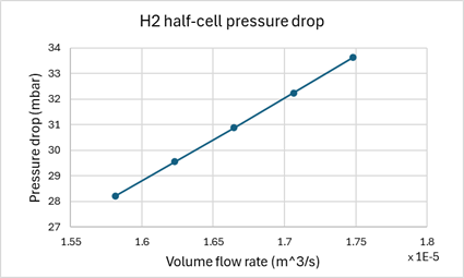
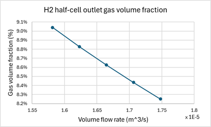
Figure 2. Half cell pressure drop as a function of inlet flow rate (left), outlet gas volume fraction as a function of inlet flow rate (right)
To generate the ROM, a series of sensitivity analyses are conducted by varying the inlet flow rate and recording the corresponding flow characteristics at the half-cell level. This methodology enables the creation of accurate, data-driven models that significantly reduce computational time while maintaining fidelity. As a result, manifold performance can be evaluated under a wide range of operating conditions without the need to rerun full CFD simulations.
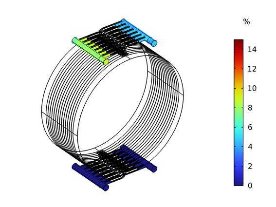
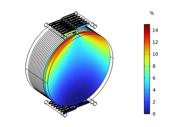
The ROM is implemented in COMSOL using built-in interpolation functions, as illustrated in Figure 2, which shows the flow vs. pressure drop (left) and flow vs. gas volume fraction (right) relationships. The model facilitates the simulation of both liquid and gas distribution throughout the stack’s inlet and outlet manifolds. Furthermore, it enables evaluation of critical design aspects such as electrolyte maldistribution and gas accumulation, which are essential for achieving uniform and efficient stack operation. An example of the gas volume fraction distribution in the manifold is presented in Figure 3.
3. Stack-Scale Electrochemical Model
The top layer of the simulation framework consists of a lumped electrochemical model that represents the entire electrolyzer stack. This model integrates the outputs from the manifold reduced-order models (ROMs), particularly the distributions of flow rate and gas volume fraction, and uses these inputs to compute local current density, cell voltage, ionic resistance, and shunt currents across the stack.
To account for performance-degrading effects such as gas-induced conductivity loss, the model applies the Bruggeman correction, which adjusts local ionic conductivity based on the gas volume fraction in each region. The spatial mapping of variables from the manifold and half-cell models is achieved through COMSOL’s with-sol and general extrusion operators. These tools enable the accurate transfer of physical quantities across the different components of the simulation framework.
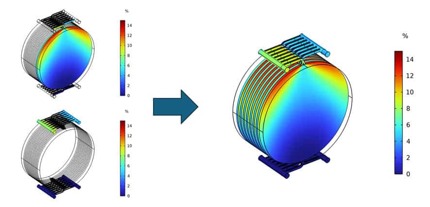
The resulting model allows for the identification of resistive losses caused by gas blockage and non-uniform current pathways, both of which are detrimental to stack performance. A visualization of gas volume fraction across all cells in the stack, including the inlet and outlet manifolds, is shown in Figure 4. These distributions are mapped directly from the preceding CFD and ROM-based simulations, demonstrating the integration of multiscale physical effects into the electrochemical domain.
Simulation Setup and Initial Validation
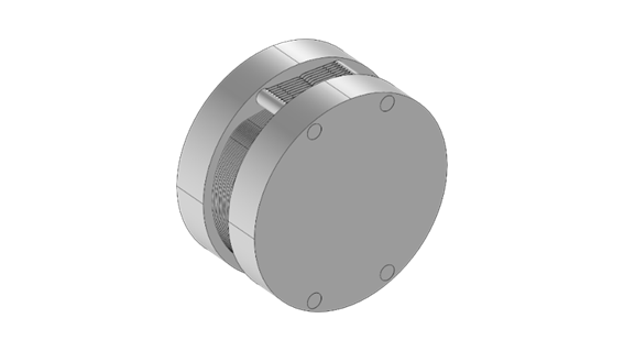
All simulations were carried out using COMSOL Multiphysics®, employing the CFD, Electrochemistry, and Multiphysics modules to capture the necessary physics and enable solution mapping across model layers. The modelled electrolyzer stack consists of seven circular cells, each 0.35 meters in diameter, connected in series and featuring single inlet and outlet manifolds on both the anode and cathode sides as shown in Figure 5. To reduce computational expense while preserving critical transport features, reduced-order models (ROMs) were constructed by conducting a series of CFD simulations across varying inlet flow rates. Interpolation functions were fitted to these results to represent key relationships, such as flow rate versus pressure drop and gas volume fraction. These ROMs were embedded into the manifold model using COMSOL’s interpolation features. The coupling strategy integrates data from the CFD-based half-cell models into the manifold ROMs, whose outputs namely flow distribution and gas phase data are subsequently mapped into a lumped electrochemical model at the stack scale. For simplicity and consistency, all cells are assumed to be geometrically and functionally identical in the present implementation.
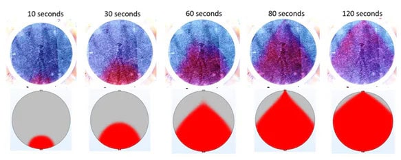
As an initial step in validating the single cell model used in this framework, preliminary simulation results were benchmarked against experimental observations, as documented in a collaborative study by Stargate Hydrogen [1]. In this validation exercise, a transparent single cell electrolyzer setup was used to visualize real-time electrolyte flow patterns through the injection of coloured dye. The CFD simulation results, which did not initially include gas evolution, closely matched the experimental images in terms of plume shape and flow dynamics as shown in Figure 6. A subsequent phase of the simulation incorporated two-phase flow by modelling gas evolution inside the cell, further increasing the fidelity and computational complexity. These simulations demonstrated realistic gas accumulation behaviour consistent with experimental expectations, particularly hydrogen stratification near the top of the cell. While this study provides a promising foundation for model credibility, further validation with full-stack experimental data is planned as part of future work.
Results
Electrochemical Performance
The simulation results demonstrate that local current distributions within the stack are strongly correlated with the gas volume fraction in the electrolyte. Elevated gas content increases ionic resistance, which in turn reduces electrochemical performance. Flow maldistribution within the inlet and outlet manifolds also contributes to non-uniform distribution of electrolyte and gas, resulting in current density hot-spots and efficiency losses.
Furthermore, Shunt currents arise due to the voltage difference between the first and last cells in the stack, creating unintended current paths through the shared electrolyte channels. While these currents do not directly contribute to useful electrochemical reactions, they represent parasitic losses that reduce the overall current efficiency of the system.
Figure 7 presents 3D simulation outputs from the electrochemical model, the left image shows shunt current distribution in the manifold color-coded by voltage, while the right image displays the corresponding voltage distribution across all cells in the stack. The model facilitates detailed investigation of shunt current effects by enabling or disabling the relevant electrochemical physics or domains, thereby allowing quantitative estimation of the associated efficiency losses and supporting the development of design strategies to minimize these effects.
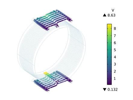
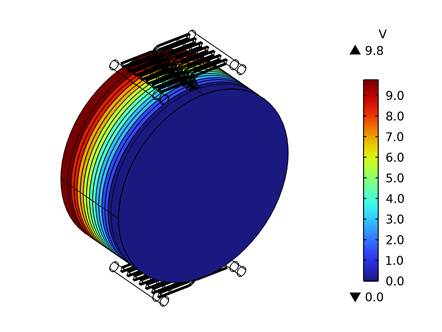
Figure 7. Shunt current distribution in the manifold color-coded by voltage (left) and voltage distribution across all cells in the stack (right)
Effect of Gravity
The inclusion of gravity in the multiphase CFD simulations reveals a buoyancy-driven accumulation of gas bubbles toward the top of each cell. This leads to vertical non-uniformities in gas distribution, which in turn alters both flow profiles and ionic resistance within the cell. Such gravitational effects are particularly critical for large-diameter or vertically oriented stacks, where stratification can significantly impact performance consistency.
Figure 8 illustrates these effects: the left image shows the gas volume fraction distribution in the first cell and manifold with gravity enabled, where a clear concentration of gas is observed near the outlet at the top. In contrast, the right image shows the gas distribution across the stack and manifold without gravity, representing the idealized scenario used in all other simulations in this study. These images underscore the influence of buoyancy on gas transport and support the decision to exclude gravity from the remainder of the analysis to focus on fundamental flow behavior under controlled conditions.
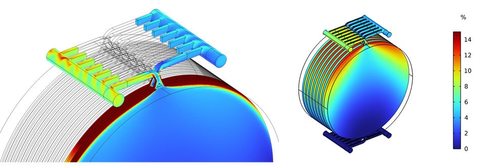
Figure 8. Gas volume fraction distribution in the first cell and manifold with gravity enabled (left) and across the stack and manifold without gravity
Digital Twin Relevance
The use of reduced-order models (ROMs) in the simulation framework significantly decreases computational time by orders of magnitude compared to full-scale CFD, making it feasible to predict stack behaviour in near real-time. The hierarchical mapping strategy enables the integration of small-scale transport phenomena, such as local gas volume fractions and flow maldistribution, into large-scale stack models without compromising accuracy. This modelling approach establishes a robust foundation for the development of industrial digital twin systems, supporting future implementation of real-time monitoring, diagnostics, and control of alkaline electrolyzer stacks.
Conclusion
This paper presents a comprehensive multiscale and multiphysics simulation framework for alkaline electrolyzer stacks. By integrating detailed CFD modeling at the cell level with reduced-order models at the manifold and stack scales, the framework captures essential physical phenomena while enabling computationally efficient performance prediction. The methodology facilitates rapid design iteration, robust optimization, and paves the way for real-time digital twin deployment.
Although the framework’s capabilities are demonstrated using a 7-cell industrial stack, its modularity allows adaptation to other geometries and configurations. The presented results validate the approach’s accuracy and practical relevance. Future work will extend this framework to include thermal effects, electrode degradation, and real-time operational data integration.
Ultimately, this methodology supports the accelerated development and scaling of high-efficiency alkaline electrolyzer, aligning with global efforts toward sustainable hydrogen production.
References
[1] Stargate Hydrogen Blog. Improving stack efficiency with digital simulation models. https://stargatehydrogen.com/blog/improving-stack-efficiency/
[2] COMSOL Multiphysics® documentation and Application Gallery
Acknowledgement
This work was conducted as part of ENDURE; a project is supported by the Clean Hydrogen Partnership and its members (grant agreement 101137925, HORIZON-JTI[1]CLEANH2-2023-1). Co-funded by the European Union. Views and opinions expressed are however those of the author(s) only and do not necessarily reflect those of the European Union or Clean Hydrogen JU. Neither the European Union nor the granting authority can be held responsible for them.