MESH, short for “Large-scale energy storage systems based on high-temperature solid oxide electrolysis cells and biogas methanation technologies,” aims to demonstrate a Power-to-X (PtX) concept for biogas methanation and storage of surplus renewable electricity. In the MESH project, the conventional galvanostatic or potentiostatic SOEC operation is substituted with a pulsed operation where an AC current (or voltage) is applied on top of a DC current (or voltage), an operating mode referred to as AC: DC operation which can mitigate temperature variations within the cell. By cycling asymmetrically around the open-circuit voltage (OCV) and operating most of the time in the electrolysis mode, the technique can be applied to PtX for the renewable production of fuels and chemicals.
This project, funded by Innovation Fund Denmark, involves collaboration with esteemed partners such as Aalborg University – Department of Energy Technology, Technical University of Denmark – Department of Mechanical Engineering, Dynelectro ApS, Resolvent Denmark P/S, and Evida Service Nord A/S.
Work Package 2.3 focuses on modelling Solid Oxide Fuel Cells (SOFC) and Solid Oxide Electrolysis Cells (SOEC) using the AC:DC operating method. The tasks involve developing models for AC: DC operated cells in both 2D and 3D configurations, leading to the creation of a COMSOL application dedicated to AC: DC operated cells modelling. The study extends the in-house developed 3D ‘box model’1 to AC: DC operation. Originally, the project aimed to develop a 2D model for AC: DC operation. However, as some effects cannot be fully investigated in 2D, such as the flow distribution in the depth direction or the temperature distribution in the future stack, a 3D model was also developed during the project. This enables the construction of stack models from this single-cell 3D model. The model has been validated against experimental results under the same operating conditions.
AC: DC operated cells modelling in 2D
A model describing a single cell in 2D has its limitations, as outlined above, but also allows for a more accurate description of the cell in other manners. The 2D model can account for the flow distribution inside the porous electrodes, giving corrections to the electrochemical Nernst potential, caused by localized starvation of the electrode. It also is fast enough to simulate and resolve the timesteps, such that it is possible to calculate the transient development of the cell during a single cycle and the transient development of the cell as it reaches thermal equilibrium over many thousands of cycles. This is done by using an efficient time-stepping algorithm for calculating and propagating the solutions in time. The model was developed in-house by resolvent, fitted to measurements done by Dynelectro in both the DC and AC: DC regime, and adapted to the specific case in the MESH project by investigating the effects of having higher pressure in the cell.
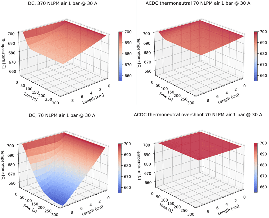
When running in DC, the airflow is used to heat the cell. Therefore, when throttling the flowrate down the temperature drops across the length of the cell when running in the endothermic range, in this specific case seen on Figure 2 at 30 amps. By going to AC: DC it is possible to maintain a much more even temperature across the cell. These simulations were run at ambient pressure.
AC: DC operated cells modelling in 3D
In this study, the inhouse developed 3D box model is used as the base model, and the AC: DC operation is included on top of the existing solid oxide cell features. The 3D box model is crafted using the homogenization approach, where various internal components of the stack (e.g., cells, gas channels) are collectively represented within a single computational volume, effectively capturing their combined response. The model can be run in electrolysis mode or fuel cell mode depending on the application. Although the current model version is in a steady state, it is noteworthy that the conventional partial differential equations employed can be reformulated as time-dependent. To solve these equations, we have utilized the finite element method (FEM) with the commercially available software, COMSOL Multiphysics. But, the modelling of the AC: DC operation requires resolving it in very fine timesteps, in the order of milliseconds. Simulating with this resolution for the developed 3D box model for a few minutes in real time would take months to years of calculation time, which is not feasible. So, a time-averaging approach is introduced in the box model to accommodate the AC: DC operation conditions.
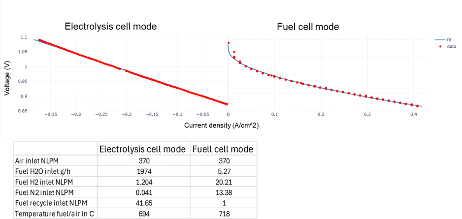
The Area-Specific Resistance (ASR) value in the box model needs to be tuned to reflect the cell characteristics. Measurements were conducted on the stack by Dynelectro under DC operating conditions. In the measurement sequence, there were parts that were ramping up and down in electrolysis cell (EC) and fuel cell (FC) mode. Since these ramping procedures took place over a few minutes, they proved ideal for fitting parameters used in the simulation, as the temperature did not have a chance to change drastically over the short time scale. To validate the model with the specific stack operated by Dynelectro, simulations, and measurements were combined at the same operating conditions to determine whether the model correctly predicted the temperature-stable AC: DC operation. The ASR fit is depicted in Figure 3. Currently, the model is only fitted with one set of operating conditions. For a complete functional box model, the model needs to be fitted for a range of temperatures and fuel compositions.
The equivalent current in the AC: DC operation can indeed be computed by averaging the current over time using the duty cycle. Then, the 3D model can be run in a steady state at this current to calculate reaction rates and resultant species compositions. However, using this equivalent current to simulate the heat generation in the SOEC model yields a different result. This is because the equivalent current typically results in a voltage lower than the EC mode voltage, leading to a more endothermic reaction.
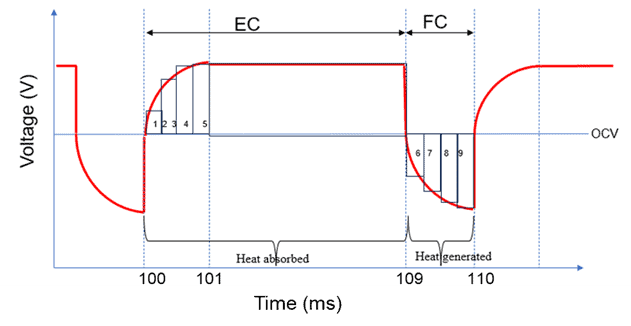
To address this issue, it’s essential to simulate the SOEC model separately in EC mode and FC mode, this allows us to accurately predict the heat generation in electrolysis and fuel cell operation. Since there’s a transition phase between the EC and FC modes, a simple time-averaging approach for heat transfer won’t be valid. Instead, we can use an interpolation function to model this transition zone and calculate the time average heat transfer without modelling a transient simulation, as shown in Figure 4. The duration of the transition phase is related to the characteristic time constant of the cell and is a function of the electrode thickness and effective diffusivity. Currently, this value needs to be inputted into the model as a parameter. The duration of the transition zone can be measured during the AC: DC operation of the cell.
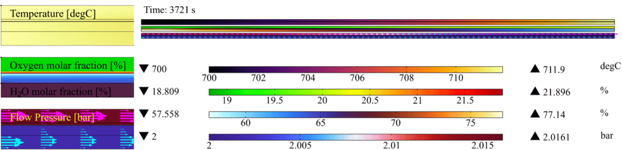
The fitted model was used to simulate the system with a 370 normal liter per minute (NLPM) air flow rate, and the results are shown in Figure 5. At this high flow rate, the air temperature maintains the system at a consistent temperature throughout the cell, minimizing the effect of the endothermic electrolysis process. Therefore, the temperature does not fall below 684 degrees Celsius at the far end of the cell, despite operating at 0.37 A/cm2 in the endothermic part of the electrolysis mode. Both experimental measurements and the simulation model predict the same temperature drop under these operating conditions.
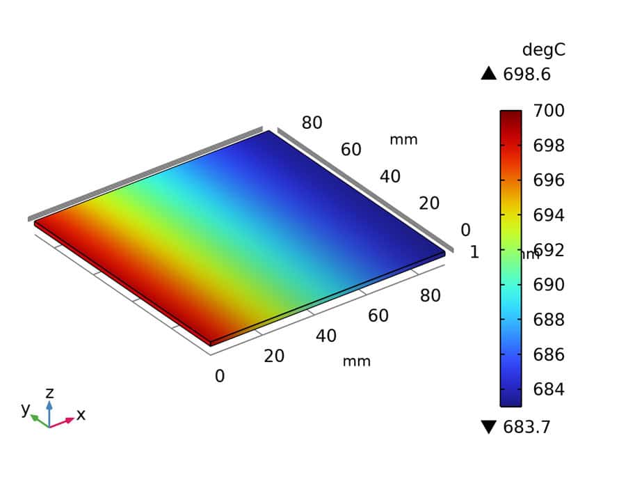
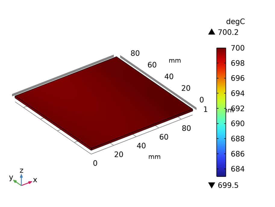
Figure 5. The temperature profile with air flow rate 370 NLPM and DC operation @0.37A/cm2 (left), air flow rate 370 NLPM and AC: DC operation @0.37A/cm2 equivalent (right).
The cell is further run in the AC: DC mode, keeping a 0.37 A/cm² equivalent current density in the cell. The current densities used in the electrolysis and fuel cell modes are 0.5 A/cm² and 0.2 A/cm², respectively, with an 80.9% duty cycle (percentage of time in EC mode) and a cycle frequency of 90 Hz. With the AC: DC operation, the system now operates more or less at a constant temperature without any large temperature drop across the cell, and this is done without completely relying on the heat supplied by the airflow. The temperature profile is shown in Figure 5.
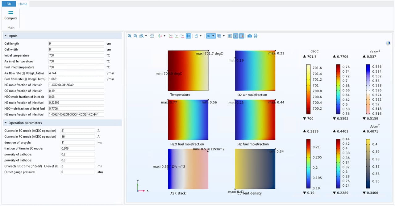
AC: DC operated cells modelling Tool (COMSOL application)
A COMSOL application has been developed for modelling AC: DC operated cells, based on the 3D model created in Task 2. The tool can take input parameters from the user, such as initial conditions and operating parameters. It is capable of running in EC mode, FC mode, or AC: DC mode by varying the operation parameters. For instance, setting the ‘fraction of time in EC mode’ parameter to 1 runs the model in pure electrolysis mode, while a value of 0 runs the model in pure fuel cell mode. Additionally, selecting a value between 0 and 1 runs the model in AC: DC mode. Figure 6 illustrates this, where the system operates in EC mode 80.9% of the time.
Conclusion
The MESH project, funded by Innovation Fund Denmark, has made significant progress in demonstrating the Power-to-X (PtX) concept for biogas methanation and storing surplus renewable electricity. Modelling of SOFCs and SOECs using the AC: DC operating method has provided valuable insights, and by effectively balancing electrolysis and fuel cell modes, the system achieves stable operation without relying solely on external heat sources. Developing both 2D and 3D models has helped address the limitations of each approach, leading to a better understanding of cell behavior. Additionally, creating a dedicated COMSOL application for modelling AC: DC operated cells helps researchers explore different operating parameters and modes, making further experimentation and optimization easier.
Footnotes
- Box model is a 3D solid oxide cell model built using the homogenization approach, where various internal components of the stack (e.g., cells, gas channels) are collectively represented within a single computational volume, effectively capturing their combined response. ↩︎