In this blog post, we will investigate the benefit of using Finite Element Analysis (FEA) to dimension pressure vessel equipment, in order to reduce material consumption and/or design equipment that is not covered by standard design by formula approaches. This blog post assumes a design according to ASME Boiler and Pressure Vessel Code Section VIII Division 2 Part 5, but most of the methodologies demonstrated are equally applicable to other design codes e.g., EN 13445. We will also demonstrate the benefit of increasing the complexity of the analysis by utilizing nonlinear FEA. Specifically, this is illustrated by creating a loading that will cause the equipment to be unsafe according to ASME’s linear FEA criteria, but safe according to the nonlinear FEA criteria.
A standard heat exchanger is used as an example. This heat exchanger comprises the shell, tubes, two tube sheets, four baffles, and two nozzles. We will investigate the outlet nozzle of the shell side fluid.

ASME design methodologies
We will use ASME Boiler and Pressure Vessel Code Section VIII Division 2 Part 5 to ensure that the nozzle is safe for operation.
Typically, components are initially dimensioned using the design by formula (design by rule requirements) e.g., Part UHX of ASME Section VIII-Division 1 or ASME Section VIII Division 2 Part 4. These formulas are based on (semi)-analytical formulas with empirical factors for idealized geometries. Not surprisingly, this typically leads to quite conservative dimensions. Let’s say that the resulting nozzle thickness seems too high, and we would like to investigate if a thinner nozzle is acceptable. We can remove a layer of conservatism by utilizing design by analysis (design by analysis requirements), meaning numerical analysis. It should be noted that it is also entirely possible that a component is not covered by design by formula and hence design by analysis is required to even demonstrate that the component is safe for operations.
In design by analysis, several analyzes are required to be performed depending on relevant loadings, such as fluid momentum, wind, earthquake, snow loads, etc. However, for our case, they reduce to three load case combinations, since only pressure, static head, deadweight, and thermal loading are assumed:
| 1. | P + Ps + D | (Primary load case combination) |
| 2. | P + Ps + D + T | (Secondary load case combination) |
| 3. | PT + Ps + D | (Pressure test load scenario) |
Where P is the internal and external design loads, Ps is the static head from the liquid, D is the deadweight of components, T is the thermal load and PT is the hydrostatic test pressure. We will exclude the pressure test scenario in this blog post for the sake of brevity. Furthermore, we will disregard the static head, Ps for the sake of simplicity. It should be noted that ASME differentiates between design and operating loading, meaning a component/structure might be designed to be able to withstand a higher loading than it will be operating at. However, in our case, we will use the design load to dimension the nozzle. All the load case combinations can be seen in ASME Boiler and Pressure Vessel Code Section VIII Division 2 Part 5 Table 5.3.
Failure modes
Before we start to analyze the structural integrity of the nozzle, let us discuss the types of failure that can occur. In order to conclude that a component/structure is safe for operation, according to ASME, we must demonstrate protection against:
- Plastic collapse
- Local failure
- Collapse from buckling
- Failure from cyclic loading
Plastic collapse happens due to the material undergoing plastic deformation otherwise known as yielding (permanent deformation), wherein the stiffness becomes lower for ductile materials and large deformations occur. This is also referred to as a plastic hinge and leads to loss of functionality and ultimately rupture.
Local failure is related to crack initiation, where triaxiality (all principal stresses are non-zero) plays a significant role. More specifically, compression does not promote crack growth, whereas tension does. Intuitively, we can think of why metal forming works, where material undergoes large plastic deformation without fracturing.
Collapse from buckling is defined as the sudden loss of stiffness, where a small increase in the load magnitude can lead to large increase in deformation response. Collapse from buckling occurs in slender columns and thin plates subjected to in-plane compressive loads (or a special case of thin plates subjected to a shearing stress state leading to wrinkling). Since no slender section is in compression in our heat exchanger, we can disregard protection against buckling.
Failure from cyclic loading is divided into two categories: high and low cycle fatigue. Let’s assume that our heat exchanger is not exposed to any cyclic loading except for some shutdowns and startups over its lifetime. This leaves us with low cycle fatigue, where high levels of mechanical and/or thermal stresses can lead to a phenomenon called ratcheting (also commonly referred to as cyclic creep). Ratcheting is the progressive accumulation of plastic strain leading to plastic hinges.
Demonstration of protection against these failure modes is covered in the load combinations mentioned in the previous section (except for collapse from buckling which requires a bifurcation analysis). Protection against plastic collapse and local failure shall be demonstrated in load combination 1, and protection against failure from cyclic loading shall be demonstrated in load combination 2.
Now that we have covered the preliminary requirements of the ASME code, we can continue with the finite element analysis of our nozzle.
Linear finite element analysis
ASME does not provide any guidelines or specific requirements for how the finite element analysis is set up, with respect to boundary conditions and geometry. In other words, it is up to the modelling specialist to show good engineering judgment.
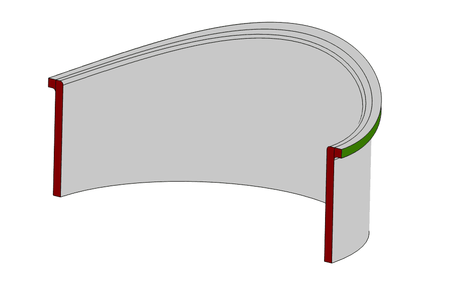
Firstly, we prepare the CAD geometry of the nozzle, where a small fragment of the shell is included for reasonable boundary conditions (see Figure 1 and Figure 2).
Now we are ready to start analyzing the performance of our nozzle. We need to perform a thermal analysis as the temperature distribution is used as input to the structural analyzes. The reason is two-fold. Firstly, temperature-dependent material properties are required. Secondly, the temperature distribution is needed to evaluate thermal stresses.
Thermal analysis
The thermal distribution can be obtained in different ways. For example, a conjugate heat transfer analysis can be performed to find the thermal fluid-structure interaction. Alternatively, heat transfer coefficients (HTC’s) can be estimated based on (semi)-analytical or empirical formulas, such as the Gnielinski correlation, which estimates the convective heat transfer coefficient for turbulent flow in a pipe. Otherwise, experimental measurements can be used to estimate the thermal distribution.
Let us assume we have experimental measurements from thermocouples stating that the temperature on the internal surface wall of the nozzle is 70 degrees Celsius and 30 degrees Celsius on the external surface wall. For simplicity, we will just apply these boundary conditions, which lead to a constant thermal gradient through the wall thickness (Figure 1).

Structural Analysis
Now that the thermal distribution is obtained, we are ready to perform the structural analyzes. Figure 2 (left) depicts the highlighted boundary conditions, where a symmetry boundary condition is applied to the surfaces located in the symmetry plane (red), while the shell fragment is fixed in all directions (green). This assumption is overly simplified but reasonable to assume since the tube sheet and baffle are nearby and will result in a stiff response and the scope of the analysis is the nozzle. Furthermore, Figure 2 (right) depicts the loading, where a pressure of 30 bar g (=3e6 Pa) acts on the internal surfaces (red), and a resulting downward half thrust force of 9.543e5 Newton at the nozzle cutoff (green). Lastly, let’s say we have been asked to demonstrate that a nozzle force is acceptable by the end-user of the equipment – it is quite common to specify fairly conservative nozzle loads to provide sufficient ‘wriggle room’ to design downstream piping equipment. The nozzle force originates from some point below the nozzle cutoff, where a 5.5e5 Newton force acts in the downward direction and a 3.75e5 Newton force acts in the perpendicular direction (in the symmetry plane, satisfying symmetry conditions).

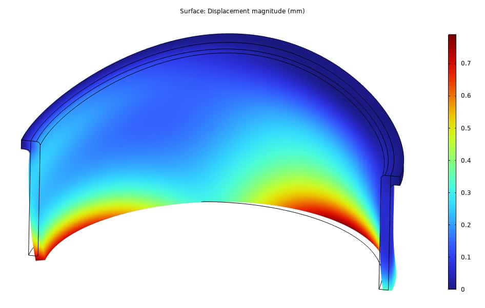
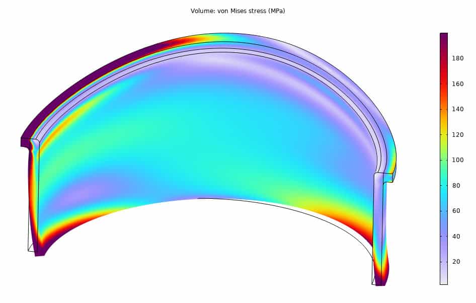
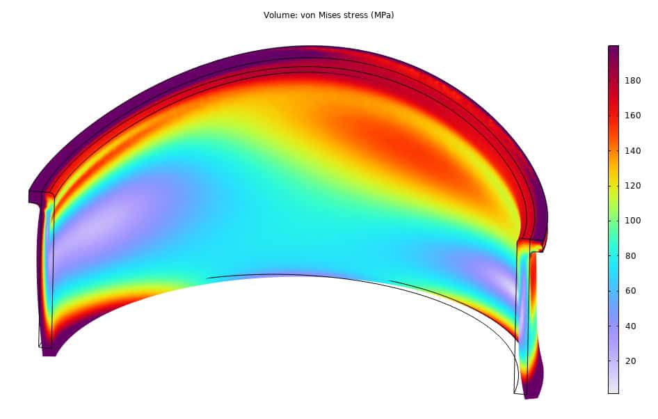
The resulting deformation and stress state of load case combination 1 (Primary) can be seen in Figure 3. In the primary load case, the effect of thermal stress is neglected. This can be done in a couple of ways, but most simply by setting the coefficient of thermal expansion of the material(s) to zero. Hence, only the effect of mechanical loads (primary loads) such as pressures, forces, and deadweight are considered.
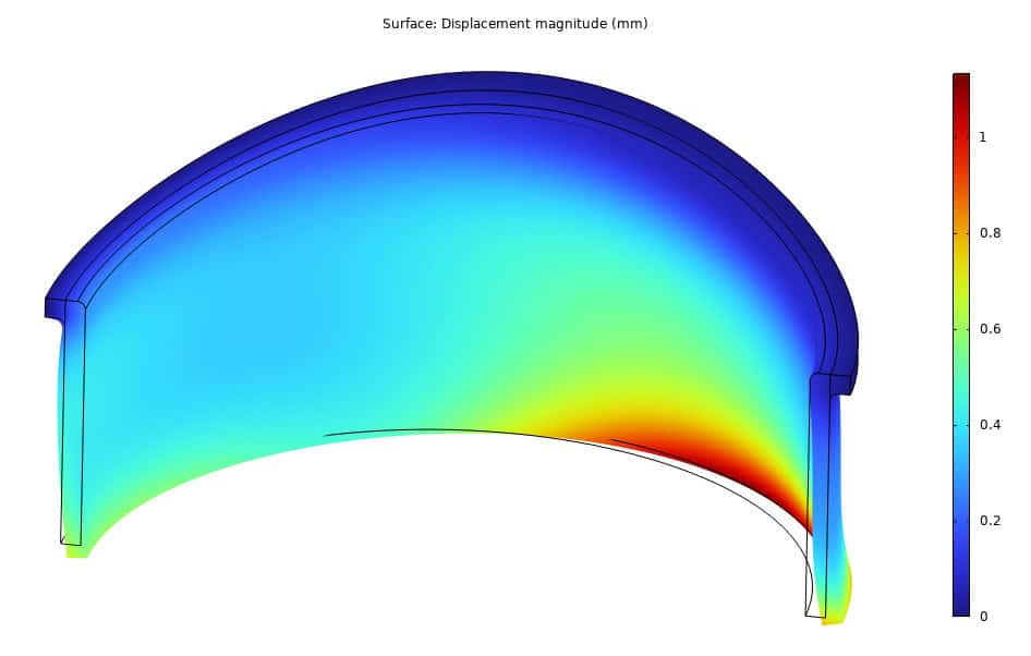
Contrarily, in load case combination 3 (Secondary), the thermal stress (secondary load) is included in the analysis. Other than the thermal expansion, the analyses are identical. The resulting deformation and stress state can be seen in Figure 4.
However, these types of results are not sufficient to demonstrate protection against plastic collapse or ratcheting according to ASME. Or in other words, safe for operation. We need to identify which types of stresses occur in the component. Specifically, we need to differentiate between membrane and bending stresses and evaluate them up against some allowable limits. We will discuss this in the next section.
Acceptance criteria: Linear finite element analysis
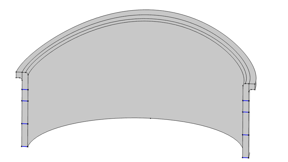
As mentioned, we need to separate the stresses into membrane and bending stresses. Specifically, we need to calculate the membrane stress and membrane plus bending stress. This is done by performing stress linearization. Stress linearization is an approximation method where a stress state is approximated by an equivalent linear stress distribution. This stress linearization is performed along a straight line through a thickness, which is commonly referred to as a stress classification line (SCL) (Blue lines in Figure 5). This procedure yields a stress state that resembles shell theory results. The component/structure’s critical locations should be covered in SCL’s to ensure that the maximum linearized membrane and bending stresses are found.
The linearized membrane stress tensor is calculated as

whereas the linearized bending stress tensor is calculated as

Lastly, calculate the equivalent von Mises stress based on the membrane and membrane plus bending stresses.
Once the equivalent linearized membrane stress, Pm, and membrane plus bending stress Pm + Pb are calculated, we need to evaluate them up against the allowable stress, S. The allowable stress is individual to each material and is temperature dependent. According to ASME, to demonstrate protection against plastic collapse, two criteria must be fulfilled. Firstly, the membrane stress from primary loads must be less than the allowable stress, Pm < S. Secondly, the membrane plus bending stress from primary loads must be less than one and half times the allowable stress, Pm + Pb < 1.5 * S. Furthermore, to demonstrate protection against ratcheting, the membrane plus bending plus secondary stress from primary plus secondary loads must be less than the maximum of three times the allowable stress or two times the yield stress, Pm + Pb + Q < max (3* S, 2 * Sy).
In the above, we simplify things a bit by omitting to differentiate between general- and local membrane stress.
The allowable stress is evaluated at the mean-metal temperature, which for the nozzle is (70 + 30) /2 = 50° C , which yields allowable stress, S = 133.2 MPa, for the nozzle made of stainless steel, specifically SA-240 304. In Table 0‑1, the resulting linearized stresses, allowable stresses, and utilization ratios can be seen.
| Type | Max. Lin. Stress [MPa] | Allowable stress [MPa] | Utilization ratio [-] | |
| Plastic Collapse | Pm | 326 | S = 133.2 | Pm / S = 2.45 |
| Plastic Collapse | Pm + Pb | 379 | 1.5 * S = 199.8 | (Pm + Pb) / (1.5 * S) = 1.81 |
| Ratcheting | Pm + Pb + Q | 403 | 3 * S = 399.6 | (Pm + Pb + Q) / (3 * S) = 1.01 |
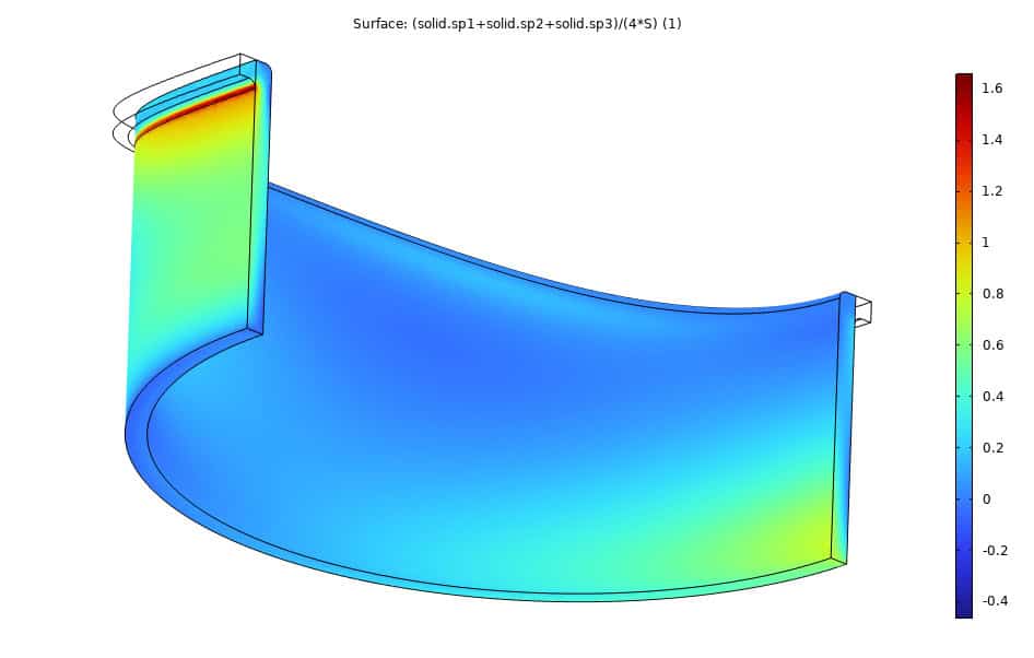
For protection against local failure, ASME’s criterion is that the algebraic sum of the principal stresses should be below four times the allowable stress, S1 + S2 + S3 <4 * S . Algebraic sum means that the sign of the number is included, and hence negative sums can occur. Nevertheless, as a negative number is always less than 4 * S, the criterion is satisfied. Figure 6 depicts the utilization ratio for protection against local failure. It can be seen that negative sums occur, which is areas dominated by compression, and thereby not susceptible to local failure. The maximum utilization ratio is above the critical value of 1.0, hence the local failure criterion is not satisfied.
From Table 01, it can be seen that the utilization ratios are above 1.0, and hence, the nozzle also fails to demonstrate protection against plastic collapse and ratcheting. To remedy this issue, we could try to increase the thickness of the nozzle and/or change the material to a better-performing grade. Alternatively, we could lower the loads and/or temperature. The first option would increase the price of the heat exchanger. The second option would lower the performance of the heat exchanger. None seem like great choices. Instead, we can remove another layer of conservatism. Remember, we already removed one layer of conservatism by going from design-by-formula to design-by-analysis. We could reduce conservatism by increasing the complexity of the finite element analysis. Specifically, by utilizing nonlinear finite element analysis.
Nonlinear finite element analysis
In the nonlinear finite element analysis, geometric and material nonlinearity is utilized. Furthermore, different approaches are required for protection against plastic collapse, local failure, and ratcheting. Firstly, we will discuss protection against plastic collapse and local failure and later protection against ratcheting. For protection against plastic collapse and local failure a kinematic hardening stress-strain curve is required. Similarly, to the linear elastic approach, several load combinations are required to be analyzed, but they have scaled loads by a factor. Nevertheless, they reduce to three cases for our nozzle:
| 1. | β * (P + Ps + D) | Plastic collapse |
| 2. | 0.88 * β * (P + Ps + D + T ) | Plastic collapse |
| 3. | 1.7 * (PT + Ps + D) | Local failure |
Where β = 2.4. As load combinations 1 and 3 are identical except, for the load factor, protection against local failure can be demonstrated using load combination 1 as it has a more conservative load factor. Furthermore, the load factor on the deadweight, D, and thermal load, T, are applied to the gravitational acceleration and coefficient of thermal expansion, respectively. All the load case combinations for can be seen in ASME Boiler and Pressure Vessel Code Section VIII Division 2 Part 5 Table 5.5.
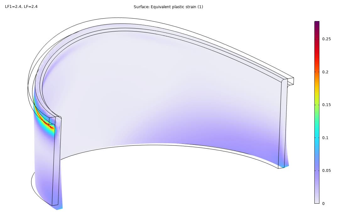
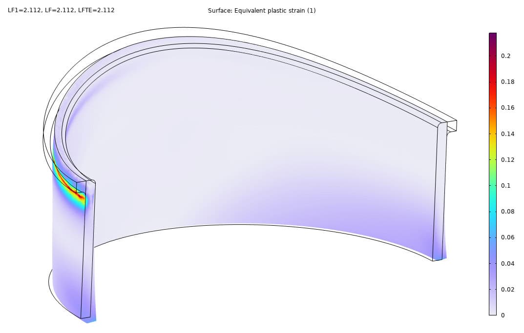
Figure 7 and Figure 8 depict the results of load combinations 1 and 2, respectively. The acceptance criteria for nonlinear FEA are two-fold. The first criterion is that the model should converge, meaning no plastic hinges or rupture occurred. The second criterion is a ‘serviceability’ criteria – in other words, do the deformations impair the operation of the equipment. For our nozzle, that would depend on upstream needs.
Figure 9 depicts the utilization ratio for protection against local failure. Here load combination 1 is utilized, where a load factor 2.4 is utilized, however, only a load factor 1.7 is required. Nevertheless, as the utilization ratio is below 1.0, protection against local failure is demonstrated. The criterion from ASME is that the plastic strain should be below some limit depending on the principal stresses, von Mises stress, and two material parameters. We will not discuss the criterion in this blogpost.

To demonstrate protection against ratcheting, another modelling approach is required. Since ratcheting is a cyclic phenomenon, cyclic loading is imposed on the component. Specifically, the component should be loaded and unloaded until the progressive accumulation of plastic strain stops (or in other words, ratcheting stops). The load combination used is the same as for the linear elastic approach:
| P + Ps + D + T | Ratcheting |
However, no load factor is applied to the load combination, although, an elastic-perfectly plastic stress-strain curve is utilized to determine the plasticity. The results of the nonlinear ratcheting analysis can be seen in Figure 10, where the last event of the load cycle is shown, i.e., the unloaded configuration after 3 cycles.

According to ASME, the acceptance criteria for demonstrating protection against ratcheting are:
- There is no plastic action (i.e., zero plastic strain incurred) in the component.
- There is an elastic core in the primary-load-bearing boundary of the component.
- There is not a permanent change in the overall dimension of the component.
Criterion 1 is usually not satisfied, otherwise, there would probably not be a need for the nonlinear ratcheting analysis, specifically not in our nozzle. Criterion 2 is satisfied in our nozzle as there is an elastic core in the cutoff. Criterion 3 could be satisfied by showcasing a plot of the nozzle diameter versus the loading cycle. Here, the deformed diameter should converge to a maximum and not increase with each cycle. Nevertheless, if any of the three criteria are met, protection against ratcheting is demonstrated.
Conclusion
In this blog post, we have showcased the benefits of increasing the complexity of the analysis in order to save on material consumption. The linear elastic analyzes show that the nozzle is not safe for operation. However, removing a layer of conservatism by increasing the complexity of the finite element analysis and utilizing nonlinear analysis shows that the same nozzle is actually safe for operations according to ASME.
The linear elastic analyzes have strict criteria to fulfill. In contrast, the nonlinear analysis criteria are less strict but relies more on the modelling specialist to showcase good engineering judgment and argue that the deformation and plasticity will not lead to loss of function or catastrophic failure.