Aim
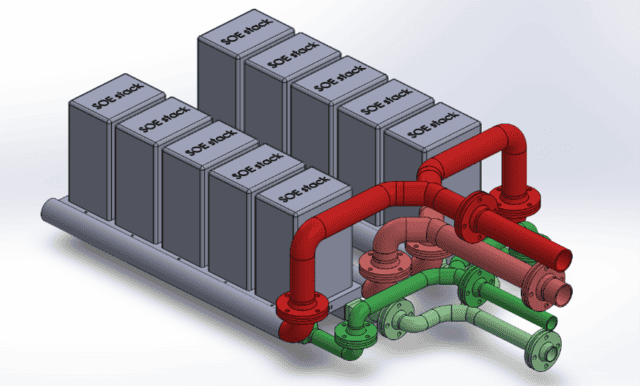
The solid oxide electrolyzer (SOE) technology for hydrogen production is rapidly developing. To meet the increasing demand for green hydrogen, upscaling the technology from single stacks to units consisting of multiple stacks is necessary. One of the key challenges concerns fuel and air distribution. Reaching uniform distribution of fuel and air across each stack improves the efficiency of such units, which is vital for efficient green hydrogen production.
One of the partners in the DynEfuel project consortium, DynElectro, has approached resolvent to perform a Computational Fluid Dynamics (CFD) analysis on the air and fuel distribution systems of their multiple-stack electrolyzer unit. The objective of this specific task was to guide the optimization of the flow distribution across the stacks and enhance the overall performance and efficiency of the electrolyzer unit.
Our customer
Dynelectro is an innovative company in the field of SOE technology. They offer a unique method for extending the life expectancy of solid oxide electrolysis (SOE). DynElectro has proprietary technologies which can reduce the cost of green hydrogen.
“DynElectro is happy to collaborate with competent modelling experts from resolvent. This helps us fast-track our development of large-scale high-efficient electrolysis technology.”
Challenge
One of the challenges encountered when upscaling electrolyzer technologies from a single stack to multiple stacks is to achieve a uniform flow distribution across the stacks while maintaining a pressure drop across the system as low as possible. Ensuring that each stack receives the same amount of fuel and air is vital for efficient hydrogen production. It is thus important to carefully design and optimize the electrolyzer unit’s fuel and air distribution systems early in the design process to maximize its performance. Parameters such as size, shape, and orientation of the fuel and air flow channels are all relevant to investigate, but building and testing prototypes with different geometrical configurations would take too long and be too costly in early design stages.
Expertise Provided
Modelling Approach
To address the challenge of achieving uniform fuel and air flow distribution across the stacks of the electrolyzer unit, a CFD analysis was conducted. A few key modelling assumptions were made:
- Individual stack pressure drop: A pressure drop was introduced into the system for each individual stack. Instead of directly modelling each stack, a two-way coupling approach was employed. This approach couples the velocity and pressure between the stack inlet and outlet on each side of the fuel/air distribution system.
- Pressure Drop Estimation: The pressure drop across each stack is a function of flow rate and was prescribed based on experimental data from an earlier project. This dynamic pressure drop allows a good representation of the change of pressure across the stacks without having to solve a complex fully-coupled Multiphysics problem for each stack.
- Gas Composition: The gas composition was assumed to remain constant throughout the analysis, as the focus was primarily on achieving uniform flow distribution.
- Stack model: In the current approach, the stacks themselves were not explicitly modelled. However, it would be possible to relax some of the above assumptions by coupling the current model with a stack model. For example, the 3D homogenized stack model discussed in a previous blog post has the benefits of solving all relevant physics at a relatively low computational cost.
Studies
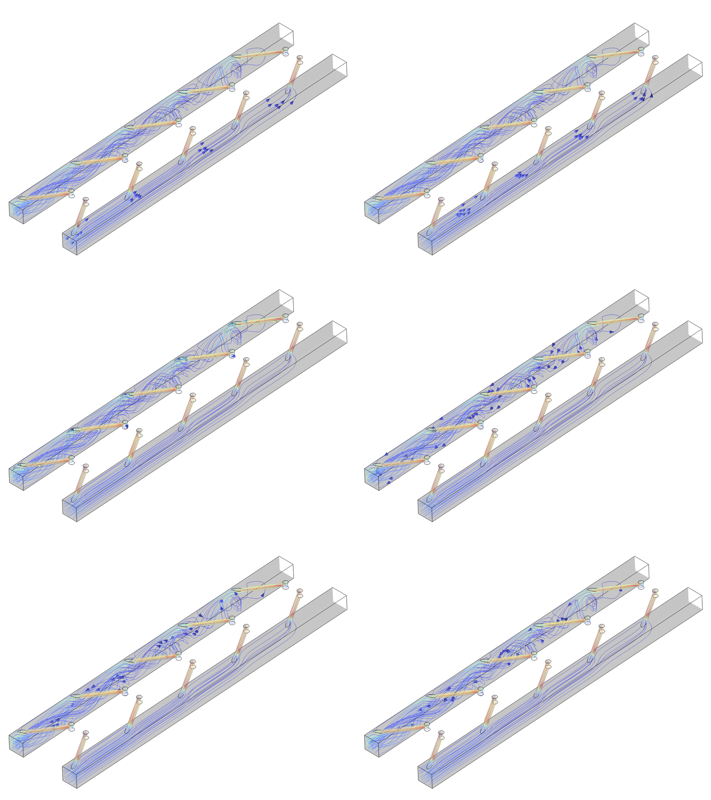
When the electrochemical reactions occurring within the stacks are not explicitly modelled, the fuel and air sides of the system are decoupled. Therefore, separate CFD analyses were done for the fuel and air sides:
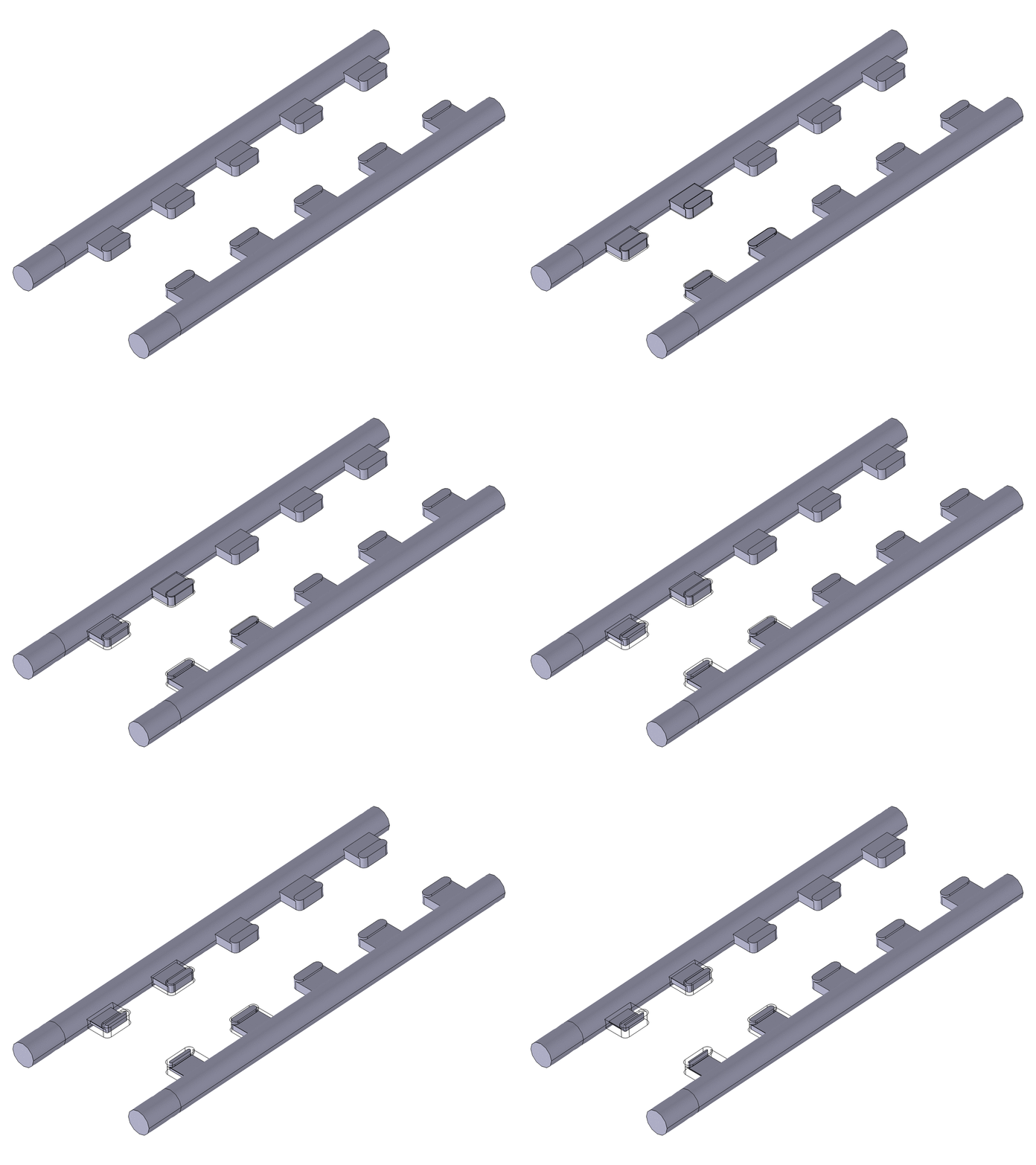
- Fuel Side: The objective was to determine the optimal orientation of the stack inlet pipes to achieve uniform fuel distribution between the stacks and minimize the pressure drop across the system. Two different designs were compared.
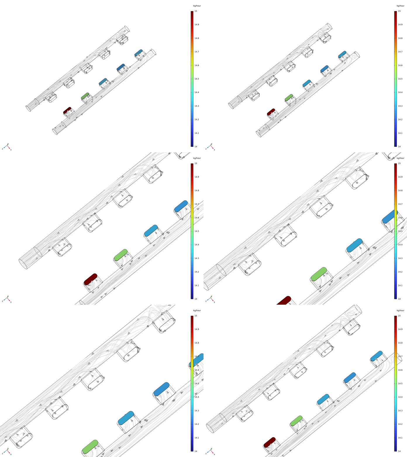
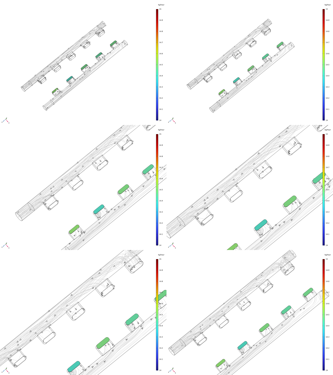
- Air Side: The size of the air flow channels proved to be a critical factor in achieving uniform air flow distribution. Initially, equal-sized channels resulted in higher flow non-uniformity. To address this, a parametric study was conducted, varying the size of the air flow channels. The final design was obtained by optimizing the channel size while keeping the channel orientation unchanged.
Results
The CFD analyses provided valuable insights into the flow distribution and pressure drop within the electrolyzer unit. The results from the studies conducted on the fuel and air sides are as follow:
- Fuel Side: The comparison of different designs for stack inlet pipe orientation helped identify the configuration that offered better fuel flow uniformity across the stacks while minimizing the pressure drop in the system.
- Air Side: The parametric study revealed that equal-sized air flow channels initially resulted in higher non-uniformity. However, by optimizing the channel size, uniform air flow distribution was achieved without changing the channel orientation.
a)
b)
Figure 4: Mass flow distribution across the stacks on the air side (a) before rescaling, and (b) after rescaling of the channels.
Benefits for the client
With CFD modelling, analysis and results, it was possible to significantly reduce the lead time and time-to-market of the electrolyzer unit by exploring multiple geometries and configurations while eliminating the need to build and test multiple fuel and airflow distribution systems. The optimized design ensured uniform fuel and airflow throughout the system, resulting in enhanced performance and efficiency of the electrolyzer unit.
Skills used
- COMSOL ® was used as the FEM simulation tool
- CFD modelling/analysis
- Turbulent flow modelling
- Parametric sweep
- Product development
Knowledge generated
CFD analysis combined with parametric studies proved to be an effective approach in addressing the challenge of achieving uniform flow distribution in electrolyzer units within the short timeframe typically encountered in early design stages. The modelling activities acted as a strong substitute/complement to experimental tests, especially since it was not possible to build multiple prototypes for testing from both a cost and time perspective.
Background
The focal point of the DynEfuel Project (Reversible power-to-X technology for the dynamic production of eFuels) is to model, design, and test a 150kW Dynamic Electrolyzer Unit (DEU) submodule with AC:DC operation technology, and integrate it into a power-to-X (PtX) plant. Ultimately, the goal is for the technology to be scaled towards large-scale PtX installations (100 MW- 1GW).
The project is co-funded by the EUDP and has the following consortium members:
- DynElectro ApS
- Siemens Gamesa Renewable Energy
- Noreco Oil Denmark A/S
- PowerCon
- Resolvent Denmark P/S
- Aalborg Universitet
- RAMBØLL DANMARK A/S
- I/S Amager Ressource center
The DynEfuel project aims to leverage the results from earlier projects (e.g., see our previous blog post) and accelerate the upscaling of the world-class electrolyzer technology for offshore wind and PtX applications such as methanol plants.
Industry
Power to X